Servos and steppers
Servos
A servo motor is a device that can position its output shaft based upon the pulse width modulated signals it receives. Servo motors can be used to move and position other components, modules and sensors. Historically, they were used in radio controlled model aeroplanes and boats and they have been widely applied in robotics. Small servos use very little power and are easy to control with an Arduino.
A servo motor has three wires connected to it and they are colour coded. The red wire should be connected to (approximately) +5 volts. The Black or brown wire should be connected to ground. The white (or orange or yellow) wire is the control wire and carries the PWM signal.
The servo motor housing contains a small electric motor, some control circuitry and a potentiometer. The potentiometer is used to check the current position of the servo arm. The servo arm position is compared to the incoming PWM signal and if necessary the motor is started and the arm moved to the required angle. The motor is run at different speeds depending on how far it needs to travel to reach equilibrium between the incoming signal and the arm position. Once the correct position has been achieved then the motor is shut down.
The servo expects a pulse on the control wire every 20 milliseconds. The length of the pulse is what determines the servo arm position. A 1.5 ms pulse leaves the servo arm at the neutral 90 degree position. A shorter pulse moves the arm proportionately towards the 0 degree position with a pulse of 0.544 ms setting the arm at 0 degrees. A longer pulse moves the arm towards the 180 degree mark which is achieved with a pulse 2.4 ms long. Some servo motors use a shorter range of timed pulses but these values are probably the most common. Always worth checking the device data sheet.
We should be able to deliver that requirement based upon our existing understanding of timers and timer interrupts but first we need to hook a servo up to our Arduino.
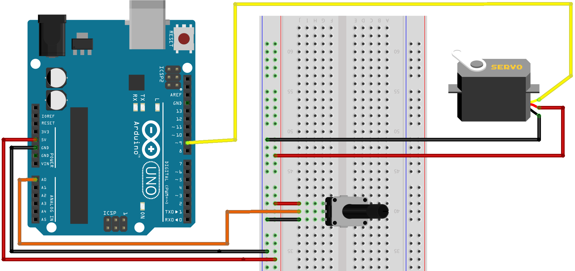
A small servo motor running with a light load can be powered directly by the Arduino board without risk and a quick Internet search will show up plenty of examples using components with a layout like the one below.
Parts List
1 servo motor
1 potentiometer with a maximum value of (say) 10K ohm (not too critical)
1 solderless breadboard
Jumper wires as required

I wrote the following program to demonstrate what has to happen to control a servo motor using an Arduino. Do not use this code for a project, it is for instructional purposes only. The code is designed to show how things work (sort of) but not how you should manage a servo in reality.
const int servoPin = 9;
byte angle = 0; // range 0 to 180
byte change = 1;
volatile bool pulseStarted = false; // flag variable
unsigned long lastMicros = micros();
unsigned long currentMicros;

void setup() {
  pinMode(servoPin, OUTPUT);
  noInterrupts();
  TCCR1A = 0;   // clear timer control registers
  TCCR1B = 0;
  TCNT1 = 0;    // Zero timer counter register for Timer1
  OCR1A = 1250; // Set the compare match register for 50Hz
  TCCR1B |= (1 << WGM12);  // CTC mode
  TCCR1B |= (1 << CS12);   // 256 prescaler
  TIMSK1 |= (1 << OCIE1A); // set timer compare interrupt
  interrupts();
}

ISR(TIMER1_COMPA_vect){         // timer compare ISR
  digitalWrite(servoPin, HIGH); // start pulse every 20ms (50hz)
  pulseStarted = true;          // set flag pulse started
}
Followed by:
void loop() {
  currentMicros = micros();
  if(pulseStarted) {
    stopPulse();
    pulseStarted = false;
  }
  // code to sweep the servo arm back and forth
  // by changing angle every 15ms (aprox)
  if((unsigned long)(currentMicros - lastMicros) >= 15000) {
    lastMicros = currentMicros;
    if(angle == 180) {
      change = -1;
    } else if(angle == 0) {
      change = 1;
    }
    angle += change;
  }
}
// function to end the pulse after required duration
void stopPulse() {
  int pulse = map(angle, 0, 180, 544, 2400); // calculate pulse time
                                             // for angle
  while(true) {
    if ((unsigned long)(micros() - currentMicros) >= pulse){
      digitalWrite(servoPin, LOW); // end pulse
      break;
    }
  }
}
The list of reasons why that is terrible code could be nearly as long as the program but we should instead concentrate on the servo specific bits. The code uses Timer1 to create an interrupt every 20ms. The interrupt sets the servo control pin HIGH. The code in loop() calls the stopPulse() function that waits for the required time (in microseconds) for the pulse based upon the required servo arm angle. Once the servo control pin has been held HIGH for the correct period of time then the pin is set LOW, terminating the pulse.
Any rational approach to this process would of course use the timer to trigger interrupts at a frequency that could be used to both start a pulse every 20ms and to terminate those pulses based upon the required servo arm position. There is an excellent Arduino Timer library available to make that straightforward but in this instance, it makes more sense to use the more specific servo library to abstract away all of the timing and control details.
Do take the time to locate and read the servo.cpp file included as a library available to the Arduino IDE. While it contains a good deal of code to deal with the range of available Arduino models and to allow the management of multiple servos the fundamentals should still be clear. You should recognise the code managing the timer and feel comfortable with the way the library converts a desired position expressed as a value in the range 0 to 180 to a timed pulse sent to the servo motor.
A demo program using this library and the breadboard based setup already illustrated is very short.
#include <Servo.h>
Servo mServo;
const int potPin = 0;
void setup() {
  mServo.attach(9);
}
void loop() {
  int potVal = analogRead(potPin);        // reads the value of the
                                          //potentiometer (0 to 1023)
  potVal = map(potVal, 0, 1023, 0, 180);  // scale to range 0 to 180
  mServo.write(potVal);                   // sets the servo position
  delay(15);                           // give the servo time to move
                                     //BUT DON’T USE DELAY() FOR REAL
}
The first line includes the Servo library and the second creates an instance of the Servo class. The setup() function attaches the servo class instance to the required servo control pin. Within the loop() function the analogue value presented by the potentiometer is evaluated and then converted to an int value in the range 0 to 180 using the handy map() function. The value is then passed to the servo write() function to be converted to a pulse length to be applied to the servo control pin.
As you make adjustments to the position of the potentiometer (and thus vary the voltage applied to the analogue pin A0) the servo arm will move in response.
An Arduino Uno and Servo library combined can support up to 12 servos simultaneously although (reasonably enough) the general PWM functionality will not be available on pins 9 and 10 (which tells us that the Servo library is using Timer1). The Arduino Mega can manage up to 48 servos simultaneously with no restriction on the use of PWM for up to 12 servos. This opens up the potential for some pretty fine mechanical output whatever model Arduino is in use.
Continuous Servo Motors
It is possible, if you have more acute eyesight and greater dexterity than me, to adapt any servo motor so that it will rotate continuously. Alternately, you can buy servos designed to run continuously. A couple of such servos combined with a pair of wheels, a ball castor (or skid) and an Arduino Nano could form almost all the hardware for a micro robot – particularly as a couple of servo motors could be powered by the same power supply used to run the Arduino. Continuous servo motors can be run using the standard Arduino Servo library. The base, 90 degree position, is interpreted by those servos as “stop”. Values greater than the 90 degree angle are “forward” with maximum speed at the equivalent of 180 degrees. The reverse is true, with values less than 90 degrees resulting in a reversed servo motor that runs at maximum speed when 0 degrees is set.
Stepper Motors
The control of stepper motors is included in this chapter because of the superficial similarities between stepper motors and servo motors. At the very least, timing is a factor with both. Servo motors compare a timed pulse to a value provided by an internal potentiometer to control the direction and speed of a motor that positions the servo arm. The servo motor power is supplied on a separate wire and the control signal power requirements are very low. A stepper motor is powered by pulses applied to the control wires. An Arduino cannot supply the required power directly through its digital output pins and so some circuitry is required to boost the low power output of the Arduino signal to the levels required to move the rotor of a stepper motor.
You can think of a stepper motor as a DC motor that moves in discrete steps. The motor position and movement is controlled by multiple internal electrical coils that can be energised in a sequence to rotate the motor in a specific direction or to hold it at a specific position. This level of control makes these motors ideal for precision positioning for such devices as printers, plotters and in robotics.
The speed of rotation can be controlled by timing the energising pulses and stepper motors have very high levels of torque at low speeds which again supports very fine positional control. Unlike servo motors, there is no inbuilt positional feedback although controlling software should be able to keep a track of cumulative pulses. Alternately, encoders can be fitted to a stepper motor to provide direct feedback on steps taken although some additional way to establish the start position may be required, depending upon the application.
Selecting a suitable stepper motor for a given application can be complex as there are many performance characteristics that might be needed to be taken into account. For our immediate purpose of exploring stepper motor control all we need is a low cost 4 phase stepper motor and something to “drive” it.
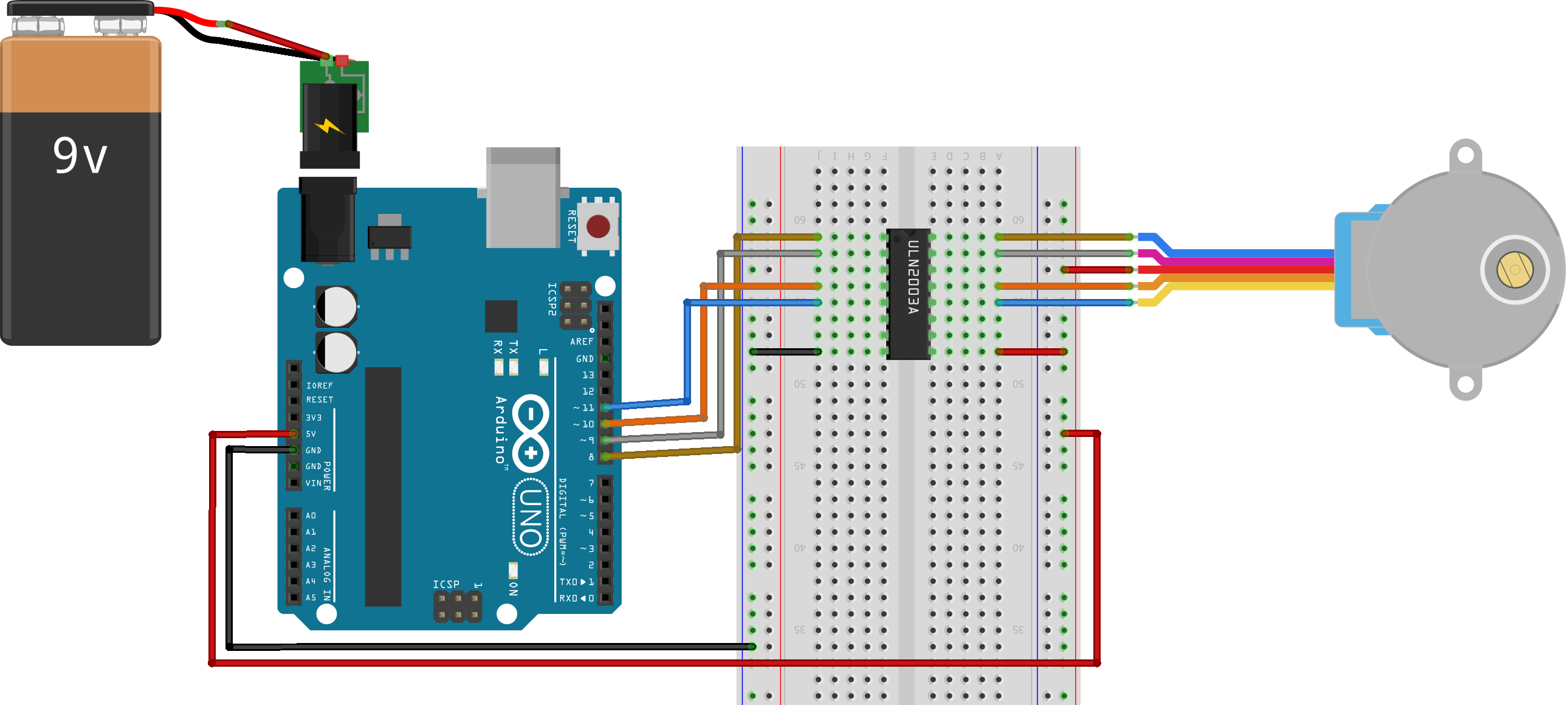
In most cases you are probably going to use a motor driver shield but in the interests of some deeper understanding let me introduce the ULN2003A chip. The ULN2003 describes itself as a high voltage and high current Darlington array IC. What that means is that if we provide the chip with a good power supply it can take a low power input and provide a high power output. A single chip can amplify seven distinct connections. We can thus feed a low power pulse from an Arduino into one side of the chip and get a high power pulse out of the associated connection and use that to drive one of the coils of a stepper motor. As we are using a four phase unipolar motor we will be using four of the ULN2003 inputs and four of the outputs to get things spinning.
Parts List
1 4 phase 5v stepper motor
1 ULN2003A chip (plus an optional dip 16 socket)
1 breadboard
1 external power supply for the Arduino
Jumper wires as required

If you are going to power the stepper motor via the Arduino then you must provide an external power supply and make sure the board is powered up using that supply before connecting the USB socket to upload a control program. I used a 9 volt battery connected to a plug for the Arduino power socket for my first tests and this proved adequate for the motor I used.
The Arduino IDE installation includes a stepper motor control library and some example programs to run a stepper motor. You may need to adjust the default Arduino pin settings and you will certainly need to set the number of steps required for a single revolution of the stepper motor. This will be on the motor data sheet or should be calculated from the step angle and the gearbox reduction ratio. As an example, a step angle of 5.625 would give 360/5.625 which is 64 steps for a single rotation of the motor and this should be multiplied by the gear ratio to get the number of steps for a single rotation of the output. You might also have to adjust the speed setting to a lower value than the ones used by the example programs presented by the Arduino IDE.
The stepper.cpp file (and associated Stepper.h file) can be located within the folders forming part of the Arduino IDE installation. Take a look at the Stepper.cpp file as it is straightforward code and you should have no difficulty in following how a step sequence is encoded as a sequence of pulses applied to the selected Arduino pins – with variations for the different number of control wires in use.
The step sequence for a four wire stepper motor is commonly as follows:
| Step | Wire 1 | Wire 2 | Wire 3 | Wire 4 |
| 1 | Pin HIGH | Pin LOW | Pin HIGH | Pin LOW |
| 2 | Pin LOW | Pin HIGH | Pin HIGH | Pin LOW |
| 3 | Pin LOW | Pin HIGH | Pin LOW | Pin HIGH |
| 4 | Pin HIGH | Pin LOW | Pin LOW | Pin HIGH |
The steps are repeated until the desired rotation is accomplished. Reversing the stepper motor simply requires executing the steps in reverse order.
Here is a sample from the Stepper library code which neatly matches the table shown above.
if (this->pin_count == 4) {
    switch (thisStep) {
      case 0:  // 1010
        digitalWrite(motor_pin_1, HIGH);
        digitalWrite(motor_pin_2, LOW);
        digitalWrite(motor_pin_3, HIGH);
        digitalWrite(motor_pin_4, LOW);
      break;
      case 1:  // 0110
        digitalWrite(motor_pin_1, LOW);
        digitalWrite(motor_pin_2, HIGH);
        digitalWrite(motor_pin_3, HIGH);
        digitalWrite(motor_pin_4, LOW);
      break;
      case 2:  //0101
        digitalWrite(motor_pin_1, LOW);
        digitalWrite(motor_pin_2, HIGH);
        digitalWrite(motor_pin_3, LOW);
        digitalWrite(motor_pin_4, HIGH);
      break;
      case 3:  //1001
        digitalWrite(motor_pin_1, HIGH);
        digitalWrite(motor_pin_2, LOW);
        digitalWrite(motor_pin_3, LOW);
        digitalWrite(motor_pin_4, HIGH);
      break;
    }
}
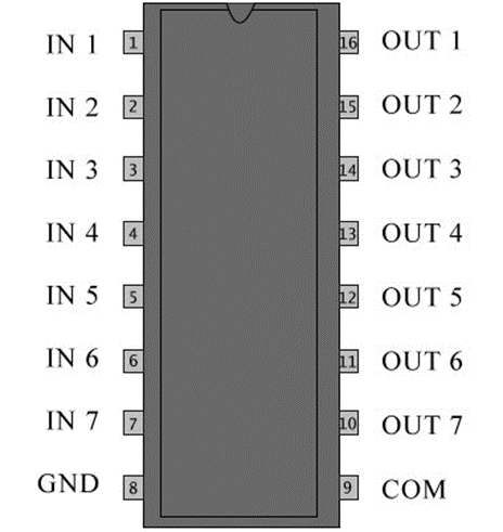
The ULN2003 chip pinout diagram shows the seven sets of connections, the ground pin and the COM pin to connect the positive power line for the output pins. The small mark at one end of the chip will establish the correct orientation.

I am sure that you can see many additional uses for the ULN2003 chip for supplying power under the control of an Arduino to a wide range of devices. Back to the stepper though. The following program is pretty similar to one of the example programs supplied with the Stepper.h library available as standard from the Arduino IDE.
#include <Stepper.h>
const int stepsPerRev = 200;  // change this for motor step angle
                              // and any gearbox ratio
Stepper mStepper(stepsPerRev, 8, 9, 10, 11);
void setup() {
  mStepper.setSpeed(30); // 30 rpm
  Serial.begin(115200);
}
void loop() {
  // step one rev at set speed
  Serial.println("Forward");
  mStepper.step(stepsPerRev);
  delay(500);
  // reverse with negative step value
  Serial.println("Backwards");
  mStepper.step(-stepsPerRev);
  delay(500);
}
The program creates an instance of the Stepper class with the class constructor (see later chapter on C++) being passed the number of steps per revolution and the control pins to use for the step pulses. The speed is then set and then the loop() function steps a revolution in each direction before repeating.
Half Stepper
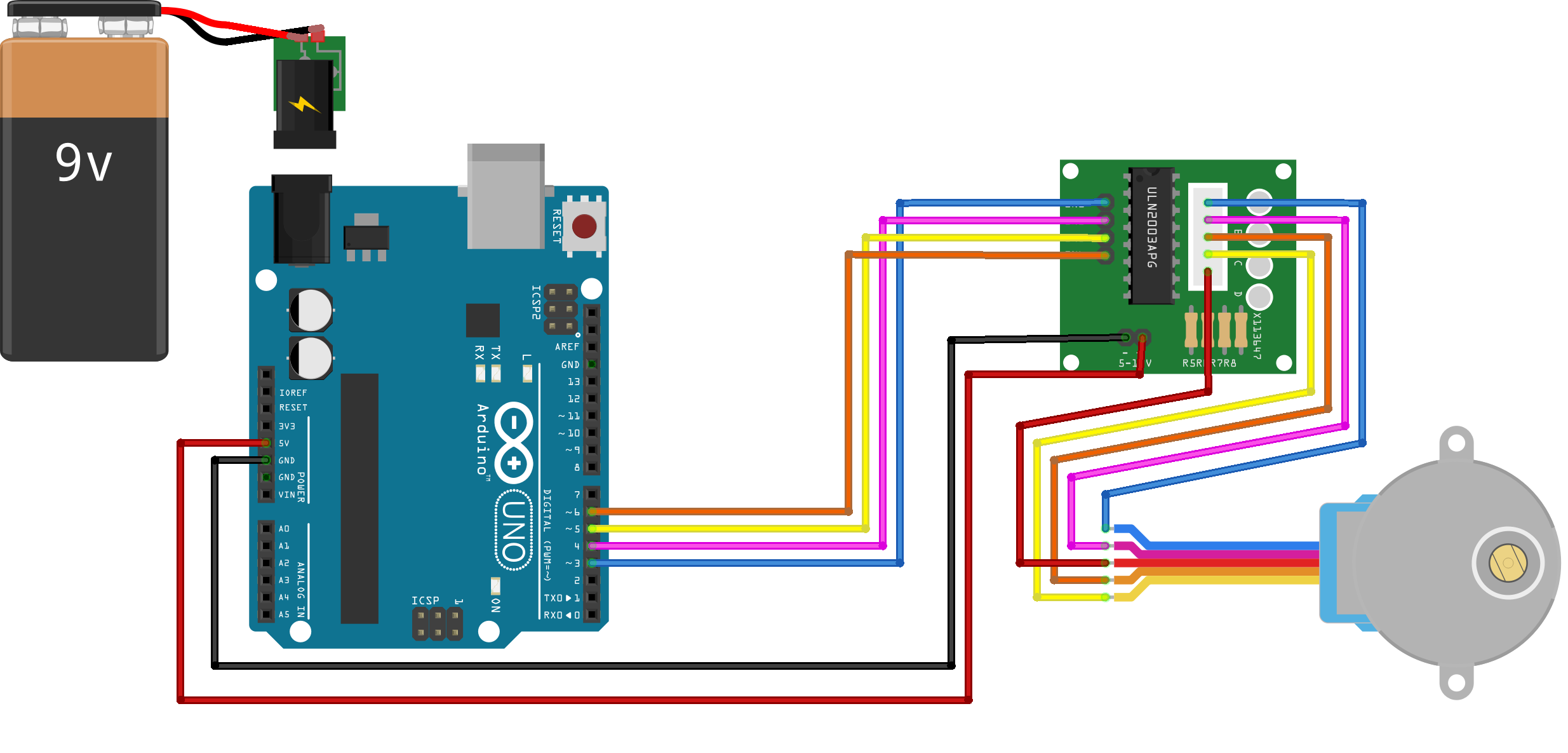
If you purchased one of the widely available 5v 5 wire 28BYJ-48 stepper motors that come packaged with a control board that mounts a ULN2003 chip then the driver board and motor should be connected to your Arduino as shown in the diagram below. These driver boards are great because they include four LEDs that pulse along with the relevant control wire so you can see what is going on (well at low speeds anyway).

You might find a breadboard handy to make some of the connections but I did not find it necessary to use one. The motor wires are connected to the driver board with a keyed plug and it is just a case of hooking up jumper wires from the Arduino power and control pins to the clearly marked pins on the driver board. Again, an external power source is required for the Arduino so that it can deliver power to the stepper motor driver board.
If you get things hooked up as shown and run one or other of the Stepper Motor example programs that use the Stepper library then you will probably be disappointed by the results. The motor will be way slower than expected and, in many instances, will not reverse direction. A look at the data sheet for this motor should explain the issue – in particular the switching sequence table. It looks something like:
| Lead Wire | Pulses in steps left to right as indicated | |||||||
| 1 | 2 | 3 | 4 | 5 | 6 | 7 | 8 | |
| 4 Orange | _ | _ | _ | |||||
| 3 Yellow | _ | _ | _ | |||||
| 2 Pink | _ | _ | _ | |||||
| 1 Blue | _ | _ | _ | |||||
Which tells us that this motor is a “half stepper” and that pulses need to be applied in sequence rather than pulsing two wires together. Rather than working up your own code to manage this, do an Internet search for the AccelStepper library. This library can be installed alongside the other libraries in the Arduino IDE Library folder. It is feature rich and you may decide to use it for all stepper motor types rather than just for the 28BYJ-48.
The library comes with some sample programs that will quickly demonstrate the full capabilities of this low cost stepper motor.
As a taster, you might try the following demo program:
const int HALFSTEP = 8;
const int sPin1 = 3;  // connect to IN1 on the driver board
const int sPin2 = 4;  // IN2
const int sPin3 = 5;  // IN3
const int sPin4 = 6;  // IN4
AccelStepper stepper(HALFSTEP, sPin1, sPin3, sPin2, sPin4);
void setup() {
  stepper.setMaxSpeed(1000.0);
  stepper.setAcceleration(100.0);
  stepper.setSpeed(200);
  stepper.moveTo(8192); // 4 times around
}

void loop() {
  if (stepper.distanceToGo() == 0) {
    stepper.moveTo(-stepper.currentPosition());
  }
  stepper.run();
}
I used a small blob of ‘bluetack’ to place a paper arm on the drive shaft of the motor I was testing and that helped demonstrate the acceleration and deceleration delivered by the library functionality while moving the set number of steps. It also demonstrated the potential utility of these low-cost stepper motors.
Review
What is the message for an Arduino programmer when it comes to managing devices such as servos or stepper motors? It has to be, locate the best available library for the task and use that. The library code will almost always be better than “home brew” and will have been subjected to the critical bug hunting attention of a wide audience. On that thought, I would like to suggest that you should always find the time to read library code. Understanding how it works may help avoid problems when using the library and may often turn up additional features that would otherwise have been overlooked. In any case, exposing oneself to other people’s code (good or bad) is a great learning experience.
Code downloads for this chapter are available here.